CARVIN
Moderate55 steps·Original on iFixit ↗

Hyundai Accent Valve Cover Gasket Replacement

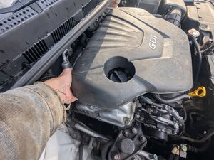
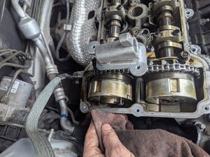
The valve cover on this 1.6L GDI engine uses a rubber gasket and does not require sealant other than two small spots where the timing cover meets the engine block. The gasket usually comes in two parts, one for the oil control valve seal and either one or two parts for the circumference of the valve cover and the seals around the spark plug cylinders.

Because this procedure requires removal of the high pressure fuel pump, the fuel pressure must be relieved before work begins.

Tools (5)

Parts (1)

  • 22441-2B610 Valve Cover Gasket+224432-B600 Rock Cover Gasket buy ↗

Step-by-step instructions

Step 1 · photo 1
1
  • Facing the front of the car, the underhood fuse box is located on the right hand side, between the battery and the fender.
Step 1 · photo 1Step 1 · photo 2
1

Remove the engine cover

  • Grasp the engine cover by the front edge.
  • Give it a firm yank upward.
Step 1 · photo 1Step 1 · photo 2Step 1 · photo 3
1

Disconnect the fuel pressure regulator electrical connector

  • Press the locking tab on the fuel pressure regulator's electrical connector and unplug it.
Step 1 · photo 1Step 1 · photo 2Step 1 · photo 3
1

Unplug the oil control valve electrical connector

  • Press the tab on the electrical connector and unplug the OCV.
Step 1 · photo 1Step 1 · photo 2
1
  • We're starting with the #4 cylinder here, but it doesn't actually matter where you start.
  • Slide the gray locking clip away from the coil to unlock the connector.
Step 1 · photo 1Step 1 · photo 2Step 1 · photo 3
1

Disconnect the breather hose

  • Use a pair of pliers to squeeze the hose clamp.
  • Move it down the hose so it is no longer over the nipple.
  • With a twisting motion, remove the hose and set it aside out of the way.
Step 2 · photo 1Step 2 · photo 2
2

Open the fuse box

  • Press the tab on the front of the fuse box.
  • And release the tab on the rear side of the fuse box.
Step 2 · photo 1Step 2 · photo 2
2
  • Grab the rear edge of the cover.
  • Yank it upward.
Step 2 · photo 1Step 2 · photo 2Step 2 · photo 3
2

Remove the fuel feed tube quick connector

  • There will almost certainly be a small amount of residual pressure in the line, so spread a shop rag under the intake and high pressure lines.
  • Disconnect the quick connect fitting.
  • In this particular car the plastic release had deteriorated and basically disintegrated when it was attempted to be used. A fitting tool was used instead to accomplish the same goal.
  • Disconnect the line.
  • On reassembly, be sure to check the low pressure fuel hose quick-connector is completely connected to the high pressure fuel pump until a confirmation 'click' sound is heard.
  • Be sure to re-check the low pressure fuel hose is completely connected to the high pressure fuel pump by pulling it after connecting.
Step 2 · photo 1Step 2 · photo 2
2

Remove the retaining bolt

  • Using a 10mm socket, remove the bolt securing the OCV.
Step 2 · photo 1Step 2 · photo 2
2

Unplug the coils

  • With the locking tab released, grasp the connector and pull it straight off.
Step 2 · photo 1
2

Remove the wiring harness

  • Using a 10 mm socket, remove the two bolts securing the wiring harness channel.
Step 3 · photo 1
3

Disable the fuel pump

  • You can remove the fuel pump fuse or the fuel pump relay; either one will accomplish your purpose.
  • Fuel pump fuse
  • Fuel pump relay
Step 3 · photo 1
3
  • The engine cover has been removed.
Step 3 · photo 1Step 3 · photo 2
3

Disconnect the high pressure fuel line

  • Using a 19 mm open end or tubing wrench, unscrew the high pressure fuel line from the high pressure fuel pump.
  • On reassembly, be sure to install the high pressure fuel pipe with the specified torque (19.5 ~ 23.9 lb-ft).
Step 3 · photo 1Step 3 · photo 2Step 3 · photo 3
3

Remove the oil control valve

  • Grasp the OCV and with a twisting motion, pull the valve out of its housing.
Step 3 · photo 1Step 3 · photo 2Step 3 · photo 3
3
  • Moving along to cylinder #3, release the connector lock and unplug the coil.
Step 3 · photo 1Step 3 · photo 2
3
  • Remove the left hand bolt.
Step 4 · photo 1Step 4 · photo 2
4
  • In this example, we are pulling the fuse rather than the relay, but again, either will do the job.
  • Using the fuse puller found in the fuse box, remove the 15A fuel pump fuse and set it aside.
Step 4 · photo 1Step 4 · photo 2
4

Remove the mounting bolts

  • The high pressure fuel pump is under significant spring pressure, so the two bolts securing it must be loosened evenly to prevent damage to the housing surface.
  • Use a 10 mm socket with a short extension to remove the bolts according to the instructions on the following pages.
Step 4 · photo 1
4
  • The oil control valve has been removed.
Step 4 · photo 1Step 4 · photo 2Step 4 · photo 3
4
  • Repeat for cylinder #2.
Step 4 · photo 1Step 4 · photo 2
4
  • Remove the right hand bolt.
Step 5 · photo 1Step 5 · photo 2
5

Start the car

  • Put the key in the ignition and start the car. There will usually be enough residual pressure in the line to allow the car to start.
Step 5 · photo 1Step 5 · photo 2
5
  • Start with one of the bolts.
  • Turn it a half turn.
Step 5 · photo 1Step 5 · photo 2Step 5 · photo 3
5
  • And, as you probably guessed, we finish up with cylinder #1.
Step 5 · photo 1Step 5 · photo 2
5
  • Fold the harness carrier away from the valve cover, out of the way.
Step 6 · photo 1Step 6 · photo 2
6

Run the car until the engine dies

  • Depending how long it's been since the car was run last, there may be quite a bit of pressure in the lines, which can let the car run for as much as three minutes, so be patient and let the car idle until it dies on its own.
  • Turn the car off and remove the key.
Step 6 · photo 1Step 6 · photo 2
6
  • Move to the other bolt.
  • Turn it 1/2 turn.
Step 6 · photo 1Step 6 · photo 2Step 6 · photo 3
6

Remove the retaining fasteners

  • Using a 10 mm socket, remove the bolt securing the #4 coil.
  • For reassembly, the tightening torque is 9.8 ~ 11.8 Nm (1.0 ~ 1.2 kgf.m, 7.2 ~ 8.7 lb-ft)
  • Note that most non-professional torque wrenches are not very accurate below about 15 ft/lbs, so it is recommended to use an in/lb wrench, in which case the torque settings to use would be from 86 to 104 lb-in.
Step 6 · photo 1Step 6 · photo 2Step 6 · photo 3
6

Disconnect the PCV hose

  • Use a pair of pliers to squeeze the hose clamp.
  • Move it down the hose so it is no longer over the nipple.
  • With a twisting motion, remove the hose and set it aside out of the way.
Step 7 · photo 1
7
  • Repeat the previous two steps until the tension on the bolts has been relieved. At that point you can remove them both.
  • When tightening the installation bolts of the high pressure fuel pump, tighten the bolts alternately in small steps (1/2 turn) after first hand tightening them.
  • Final torque on the bolts is 9.4 ~ 10.9 lb-ft. Most non-professional torque wrenches aren't very accurate below 15 ft/lbs, so if possible use a wrench calibrated in in/lbs, 113 ~ 131 lb-in.
Step 7 · photo 1Step 7 · photo 2
7
  • Repeat for cylinder #3.
Step 7 · photo 1Step 7 · photo 2
7

Remove the valve cover bolts

  • Using a 10 mm socket, remove the 19 bolts securing the valve cover to the cylinder head and OCV mount.
Step 8 · photo 1Step 8 · photo 2Step 8 · photo 3
8

Remove the high pressure fuel pump

  • The high pressure fuel pump can now be lifted off the valve cover.
Step 8 · photo 1Step 8 · photo 2
8
  • Moving along to cylinder #2, rinse and repeat.
Step 8 · photo 1Step 8 · photo 2Step 8 · photo 3
8

Remove the valve cover

  • It may be necessary to give the valve cover a tap with a rubber mallet, but generally you should be able to simply lift the valve cover off the cylinder head at this point.
  • Do not pry the valve cover off with, for instance, something like a screwdriver; you can easily damage the soft aluminum surfaces and create a situation where the valve cover cannot be sealed.
Step 9 · photo 1Step 9 · photo 2Step 9 · photo 3
9

Remove the roller tappet

  • This is easiest done with a magnetic pickup tool, but it can be removed using your finger inserted into the roller tappet and pull up on it.
  • Before installing the high pressure fuel pump, position the roller tappet in the lowest position by rotating the crankshaft. Otherwise the installation bolts may be broken because of tension of the pump spring.
Step 9 · photo 1Step 9 · photo 2
9
  • And we finish up back on cylinder #1.
Step 9 · photo 1Step 9 · photo 2
9

Clean the cylinder head surfaces

  • Wipe down the oil control valve housing to ensure the gasket mounting surface is clean.
  • If you need to scrape it, do not use metal instruments; a plastic scraper will ensure you don't damage the surface.
  • If you need to use solvent, use something like brake cleaner that won't leave a residue.
Step 10 · photo 1Step 10 · photo 2
10

Remove the coils

  • Moving back to the #4 cylinder, grasp the coil and pull straight up to remove it.
Step 10 · photo 1Step 10 · photo 2
10
  • Here we're wiping down the timing cover surfaces.
Step 11 · photo 1Step 11 · photo 2
11
  • Likewise for the #3 coil.
Step 11 · photo 1Step 11 · photo 2Step 11 · photo 3
11
  • Now we want to wipe down the cylinder head surfaces.
  • The outside edges are clean now.
  • And the spark plug tubes are also prepared.
Step 12 · photo 1Step 12 · photo 2
12
  • We pull the #2 coil.
Step 12 · photo 1
12

Remove the old gasket

  • Flip the valve cover over and remove the old gasket. You should have the outer perimeter gasket, circles around the spark plug tubes, and the oil control valve mount as seen in this picture.
  • Clean the channels where the gasket sits to ensure a proper seal.
Step 13 · photo 1Step 13 · photo 2
13
  • And for our grand finale, we remove the coil from cylinder #1.
Step 13 · photo 1
13

Install the new gasket

  • Start with the oil control valve housing seal; press the rubber gasket into the channel.
Step 14 · photo 1
14
  • The ignition coils have been removed.
Step 14 · photo 1Step 14 · photo 2Step 14 · photo 3
14
  • Secure the spark plug hole gaskets into place.
Step 15 · photo 1Step 15 · photo 2Step 15 · photo 3
15
  • Tabs are present at intervals around the edges of the valve cover; be sure to match them up for a proper fit.
  • Go around and seat the rest of the gasket.
Step 16 · photo 1
16
  • Here we see the gasket fully installed.
Step 17 · photo 1Step 17 · photo 2Step 17 · photo 3
17

Add sealant

  • Add a small amount of gasket sealant to the joint between the cylinder head and the timing cover on each side.
Step 18 · photo 1
18

Replace the valve cover

  • Set the valve cover in place back on the cylinder head.
Step 19 · photo 1
19

Torque the valve cover bolts

  • Install the 19 bolts securing the valve cover and hand tighten them.
  • Follow the tightening sequence displayed here in two stages.
  • First tighten the fasteners in the order shown to 35 ~ 52 lb-in (2.9 ~ 4.3 lb-ft).
  • Second pass, torque the bolts to 70 ~ 86 lb-in (5.8 ~ 7.2 lb-ft).

Conclusion

To reassemble your engine, return to Step 42 and follow these instructions in reverse order.

Guide content belongs to iFixit, license CC BY-NC-SA. Open original